Thursday, March 3, 2011

ZN Line Caelestia

Hello everyone,

I am very excited to be able to show you the new ZN Line Caelestia that I will be flying at the 2011 F3A World Championships in Muncie Indiana.

This is a brand new design that has been a collaborative effort between ZN Line (Jean-Pierre Zardini is the sole owner of ZN Line), and myself. This brings many decades of F3A experience to bear on this design. I personally am extremely pleased to have been able to work with ZN on this project. I have flown ZN designed models exclusively since 2002 and have always been very happy with the quality and flying characteristics of those models. This one is sure to be no different! We have taken all the best of our experience to create the best F3A plane for todays sequences. Some of the design features include:

- No chin cowl, for reduced weight and consistent fuselage structure (electric only!)
- optimized air inlets and outlets to minimize the need to make additional cuts into the fuselage
- fuselage sides are curved to provide maximum geometric stiffness to the model
- wing/stab position, incidence, dihedral and thrust line optimized
- Wing tip fences for maximum lateral stability and improved knife edge performance without additional mounting/coupling issues (Thanks to Chip!!!)
- Tip cap on the elevator to protect the moveable surface and also aid in easier setup
- Flared rudder (smaller than Xigris) trailing edge to provide better direction stability and softer neutral feel
- Wing profile and airfoil optimized
- Fuselage profile adjusted for a balanced area distribution
- Slight anhedral stab
- Canopy base set to be parallel with fuselage “zero line” to aid in setup if needed

Designing the model in 3D Cad allowed us to control the finest detail of every parameter of the design. As well the fuse, wing, stab, rudder plugs will be cut on a CNC router based off this CAD model to ensure that all these details are retained.

The model will be produced as a full composite plane, and painted in the mold (colors etc. still to be determined), and I believe even custom paint jobs will be available.

All of the current available electric motors should fit the model without issue, obviously I will be installing the Plettenberg Advance motor, and mounts will be made to specifically mount a variety of motors.

I will continue to post more info and details as the prototype model is produced, and production models are made.

CaelestiaFinal_1.Po3mZIPpIdqN.jpg

Chad

Sunday, January 30, 2011

New Thunder Power RC 820CD Charger

Hello everyone,

I recently received one of the new 820CD charger/dischargers from the folks at TP. This is their entry into the high power charger market. Spec’s on the charger can be easily found on the net, but for F3A purposes you will be able to charge a typical 10s 5000 mAh F3A pack at approximately 4C (20A). This will provide recharge times as quickly as 15-18 minutes. Assuming of course you are able to feed it with 28V and 800W of power!

What I am going to show you in this report is how to wire up harnesses to be able to charge two (2) 10s 5000mAh Prolite V2 brick packs that have the 4mm interconnect bullets. Also how to wire two (2) Iota DLS-55 power supplies in order to give you the 28V and power required to charge these two packs in 30 minutes.

IMG_1400.nqliUsS2qh4N.jpg

Out of the box you are presented with a very nice looking package. Slightly larger than the previous 1010C charger. You will see a larger nicely backlit LCD screen with two line display, sealed raised face buttons that are easy to push yet give a positive feel. Two fans (one for each port) force heated air out the rear of the charger. Connections for the balance boards are on each side of the charger as is the mini-USB update port. You will also notice two charge ports!


IMG_1405.LYodZVI4v65B.jpg

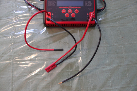
The first order of business is to get the power supplies ready for action. I have Dean’s connectors on my DLS-55’s, so it was very easy for me to wire them in series with a simple series adapter as shown in the picture. If you are not familiar with how to wire DC in series there are lots of pages on the internet to help.

IMG_1407.UmVm2XSmvm32.jpg

When done this was how mine looked. Now the Iota power supplies have a small telephone jack to boost the voltage from a float voltage to a fast charge voltage (approximately 13.6V to 14.2V). With both of these jacks plugged in you will get a too high input voltage warning on the 820CD. Remove one and leave one in, this gives you as close to 28V as possible. If you remove both your peak current will be automatically reduced slightly by the charger to compensate for the lower input voltage.

IMG_1401.i0Pm5O3X2Uv1.jpg

Now lets get to work on the charger. Here is the charger with the balance boards connected. There are connections on the balance board for all TP connectors as well as 2s to 8s connectors for other popular brands.

IMG_1403.U9I97ZsuIS3B.jpg

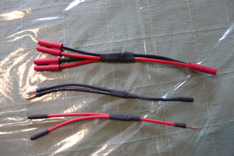
In the box comes 4 leads for making your own charge cables. The leads already have the 4mm bullets soldered to them for connecting to the charger. In order to make the leads such that you can charge a 10s brick pack with interconnects you need to solder a 4mm socket onto one of the positive leads, a 4mm male to the negative lead, and your favoured connector to the remaining two leads as shown in the picture. This process is also described in the manual.

IMG_1404.T1YkprPsrEE1.jpg

The above leads need to be connected to the charger as shown here for the correct polarity. Essentially you will be charging each 5s portion of the pack on each of the two charger ports.

IMG_1410.qE7WGorfnaQ5.jpg

In order to charge two 10s 5000 mAh brick packs you will need to build some parallel adapters. This guide assumes you understand the principles for making parallel connections. It is pretty straightforward as you are simply branching a single to a double keeping the polarity constant. You need branches for both interconnects as well as the main leads.

IMG_1412.EJQtP3FECJTx.jpg

You also need to build parallel adapters for the balance leads. I took 4 balance extensions and built these two parallel adapters. Same principles apply, you are simply branching a single wire to a double keeping the polarity the same. One note of caution on the balance leads. My leads were not all color coded the same, so it is important to ensure that you are wiring them truly in parallel and not simply by color, as in my case that would have resulted in a direct short across the leads.

IMG_1413.mFi95cl4aSm7.jpg

Now we have all our leads built, we can start connecting the packs. These are the two packs I will be using, very standard packs used in F3A. These batteries were both fully discharged, one was 37.3V and the other was 37.7V. These voltages will equalize when parallel connected. A small mismatch is not a problem, but I would be cautious if your packs are more than 5% different (37.5 to 38.5V). Typically in F3A our flights are so consistent that this is not normally a problem.

IMG_1414.l1Rcd9LKwpLr.jpg

Leaving the packs with the interconnects attached, the first thing I do is plug in the main lead parallel adapter. This will immediately equalize the voltage between the two. When I did this the voltage was about 37.5V.

IMG_1416.7UTFdeZ9Q8D8.jpg

Next break apart your interconnect leads.

IMG_1418.9uvOwFIpc8Iz.jpg

Now connect up both your positive interconnect parallel cable and your negative interconnect parallel cable as shown.

IMG_1419.GOPwjEndMKlO.jpg

You can now connect your parallel adapter cables to the charger cables we made up and installed earlier. As always double and triple check all your polarities the first time to ensure that you have made all the solder connections correct. Before you start connecting batteries, go ahead and power up your charger.

IMG_1420.aOhN0R7u74Ps.jpg

Now go ahead and connect up Group A of your balance connectors to the parallel balance adapter we made, and then to the Port 1 balancer board. It is important that Group A be connected to Port 1, because the primary negative lead from the batteries are connected to Port 1. Go ahead and do the same for Group B and Port 2.

IMG_1428.9SYGDNNgAJMS.jpg

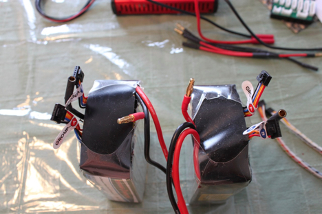
Once Group B is connected, we are ready to charge. Your final setup should look something like the picture above.

IMG_1408.kqRT3tzZ5YO3.jpg

Perform the setup on both ports (port 1 shown in the picture) to charge a 5S lipo at the maximum current possible, in my case 19A was all I could set. Set the capacity (CP) to the maximum as well so that you wont shut down on capacity limit. Ensure the balance circuit is turned ON for safety reasons.

IMG_1422.HiV9t1JXPsB8.jpg

Double check all your cell voltages before the start of the charge just to be certain everything is A-OK. With the high rates of the charger things happen very quickly!

IMG_1424.PiMAzM1nPCcd.jpg

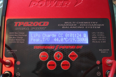
Once you are comfortable that everything is set correctly, hold down the enter key to start the charge, and repeat for the second port. The charger ramps up very fast, you can see here only 18 seconds into the charge we are already at peak current. The voltage displayed is the current battery voltage for the selected port.

IMG_1426.SrtM7F0Ech1t.jpg

There are two other screens available by pressing the +/- keys. One is the cell voltage shown here.

IMG_1427.tyOiKVeqhTV1.jpg

The other shows the chargers max temperature. During my charge the charger reached a peak of about 60 degrees C. The fans were at full speed for most of the charge duration.

IMG_1429.IGEwZb1UYEjz.jpg

5 minutes into the charge 1600 mAh has gone to the packs (800 each). I am expecting over 7000 mAh total.

IMG_1431.UZRcLaPByD5c.jpg

At 10 minutes in a little over 3000 mAh has went to the packs.

IMG_1433.mWhERSRkwzfg.jpg

15 minutes in over 4600 mAh, this is easily over halfway from a capacity standpoint. WOW!

IMG_1434.Ly7TIOs6Anzn.jpg

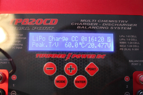
We have also reached our peak internal temperature of 60C.

IMG_1436.JbXyeXdI046O.jpg

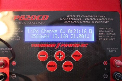
21 minutes into the charge we have put 6566 mAh into the packs, and reached peak voltage of 21V so the charger has moved to CV (constant voltage) mode.

IMG_1437.sXMHYLi5tWXs.jpg

25 minutes in the charger has ramped down to 5.5A, sent 7255 mAh into the packs and is nearing the end of the charge cycle. Remember this is for TWO (2) 10s 5000 mAh batteries!

IMG_1439.l21YK2X419n7.jpg

At just under 33 minutes the charger is finished, sending 7685 mAh (~3840 mAh each) into the packs. If you had only a single pack connected to this charge you would have completed in about 16-18 minutes. I have also done this since getting the charger (4C) charge, and it will come in very handy for those times you really need another flight!

So far I have found the 820CD very simple to use. If you are familiar with the operation of the 1010C charger then you will notice many similarities between the two with respect to operation. The construction is very good, and superior to the 1010C in almost every regard.

I have not yet tried this connected to my Honda 1000i generator. However, a 10S pack being charged at 19A is 798W peak, I expect that the Honda will have a hard time handling that amount of power. The charge current may have to be reduced slightly to allow charging from a 1000W generator. This should be more than do-able for a 2000W generator though.

To download as a PDF file click below,

http://www.mediafire.com/?gkqriqabxezxq3v

I hope you enjoyed the walk-through, if you have any questions drop me an email!

chad@f3acanada.org

Chad

Tuesday, December 28, 2010

Covering the Xigris C2

I thought I would post a small how to on covering while I am working on my ZN Line Xigris C2. I will share how I make my covering schemes, which are usually somewhat complicated. It is a fairly straight forward process and nothing to be afraid of trying.

First thing is the template. I take some time and accurately draw my color scheme fullsize. I use AutoCAD but any program that allows you do draw to scale will work fine. With AutoCAD you can plot to a DWF file, and then open with another bit of free software called Autodesk Design Review. In Design Review you can then print your drawing as tiled images so you can get full size images on 8.5”x11” paper.

IMG_0424.Wn4hOIURDT3O.jpg

Next I use a spray contact adhesive to stick the plan to heavy paper for the templates.

IMG_0425.PeMAwmDcb6RD.jpg

Now we have to let this dry a little bit so the paper doesn’t peel off the heavy paper. Don’t forget to label your colors so you get the scheme right!

While that is drying we can do some preparation that needs to be done before we do the major covering job. For all my covering I use the tools in the picture, two covering irons one with a sock and one without. The one with the sock is set to about 125 degrees C, and the other is set as hot as I can get it. A small trim tool for tight places, a heat gun which I didn’t use at all for this job. Various cutting tools, rulers, weights etc.

IMG_0427.KqZ8bGOeiBQO.jpg

I always do my covering after hinging, so I do my gap sealing and some other trim details before I do the major pieces.

To do the gap sealing you first take a piece of white and crease it in half down the length. Make sure you have plenty of extra to cover the entire gap.

IMG_0430.l2cRljjynliE.jpg

Then push that piece into the gap, and use the trim seal tool to iron it neatly in place.

IMG_0434.IIOmoxQxQ58d.jpg

Then using a sharp blade, trim the excess to be flush with the surface of the part. As a note, I gap seal both top and bottom so my hinge lines are completely weather proof.

IMG_0438.IWuPywMZAhb5.jpg

Next apply the trim to the inner face of the elevator.

IMG_0439.EQL4YZnWvwGp.jpg

Thats all the trim work that I need to do on the stab. I don’t bother too much with the very root, as its all covered up once mounted onto the fuselage.

By now the templates should be dry. So you can cut out the individual pieces. Notice that I did not cut out the small silver and blue sweeps on the bottom right. This is because this area is going to be all white, so I will first cut the white covering out with the template, then cut the sweeps from the white portion after.

IMG_0440.81BaIiyybbsV.jpg

Now trace the white profile onto the covering. Do both sides at once to save time.

IMG_0441.fIscVm9PJ6qF.jpg

Now I freehand cut with scissors the white parts out. Since they will be the first color on you must leave an allowance for the next colors to overlap. About 2mm or 1/8” is fine.

IMG_0442.Iif4gfWUHnz7.jpg

Now in order to properly locate the colors I make a second set of template trimmed to match the stab size.

IMG_0445.F5cPXbYqVv8O.jpg

I overlay that on the part, and make small pin holes to give me reference points to place the covering.

IMG_0446.LmCqX5ylaRCw.jpg

I then locate the white and yellow (yellow is cut the same way as white), as they are the two bottom colors of the scheme.

IMG_0449.IHSjCh9JcwXO.jpg

I use some masking tape around the tip to protect the bottom colors from having adhesive stuck to them. After you trim the tip colors off then you just pull this off. I find that sometimes, especially red and blue leave a lot of adhesive when they get trimmed away if you accidentally heated past where you will trim.

IMG_0450.ZCTCATSLLvI0.jpg

Then its time to cut the red. Since the red overlaps it needs an exact cut. Its best to use a piece of glass and a sharp blade to trace along the template. Its important that this cut is clean as you will see it on the finished product.

IMG_0443.04UTCu4a410K.jpg

Now apply the red using some guides to help with the alignment.

IMG_0451.hUYdnfwecyYF.jpg

Now you have to pull the covering around the tip. I use my hot iron to help with this. A lot of patience, and allowing the covering to stretch makes the tip come out wrinkle free.

IMG_0453.smpmtS5HMROI.jpg

No trim the red and yellow along the masking tape, and peel the tape off. Be careful not to cut too deep into the bottom covering. You should be left with a nice straight line. I did this one freehand.

IMG_0454.vvEdnb92aYlJ.jpg

Next I trim the LE covering. Using the edge of the glass and a sharp blade you can get a nice straight cut where you want.

IMG_0455.aNEnIP2pvZBh.jpg

Finished LE

IMG_0456.qbVDJftL83KR.jpg

Now I do the blue, this piece is small and hard to keep still. So I cut an oversized piece and peel off the backing. I spray a little water onto my glass, lay down the covering and squeegee out with a card all the water. This sticks the covering down and allows you to make accurate cuts without it moving around.

IMG_0458.gVyVGIaNUY2H.jpg

Now iron the blue in place using some guides to keep it aligned.

IMG_0461.6oTxiZPJnkaR.jpg

Next cut the silver on the glass, and aligned and iron down much the same as the blue. The silver is the final piece so every side needs to be accurate as you will see all of them.

IMG_0462.6YvwefWZOzgm.jpg

Now it is time to cut the little sweeps out of our white template.

IMG_0463.mYmgv8JOL5sf.jpg

Using the techniques above, cut the sweeps on the glass and apply them to the stab.

IMG_0465.tgaWLCdvVmiJ.jpg

Now we have to split the covering down the hinge line. To do that I first fold the hinge line to give the covering a bit of a crease.

IMG_0467.3nh6q5ouvvFz.jpg

Then with a sharp blade, I split the covering down the hinge line. I keep the surface folded a bit to help guide the blade down the line.

IMG_0468.dkb4jcrMN0Hk.jpg

Now use the trim seal tool to seal down the leftover in the hinge line.

Voila, you now have a cool looking stab :)

IMG_0469.glLuQT42JtzO.jpg

This is a quick way to get a cool scheme. All told I can do two stabs like this in about 3 hours once I have the drawing made in AutoCAD. Usually doing the drawing takes as long as covering!

Chad